 Ben Eisdorfer
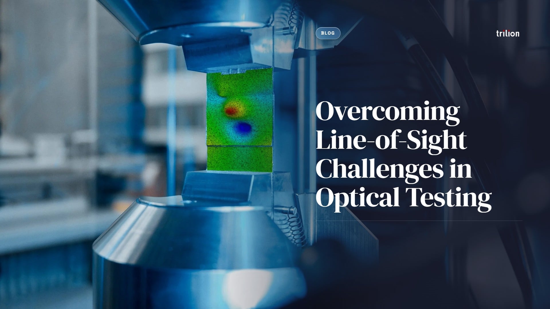
Optical measurement systems such as ARAMIS Optical Strain use digital image correlation (DIC) to capture strain, displacement, and motion across a visible surface without covering a test article with sensors and wires. While effective, this approach has one unavoidable requirement: the cameras need to see the area being measured.
That sounds obvious, but in practice a grip, bracket, cable, or even the test article itself can block the critical region, sometimes only after the test begins.
The answer is not always to accept missing data or redesign the entire test. Often, the right viewing strategy can solve the problem.
The View at the Start Is Not the View That Matters
A setup may look perfect at zero load. Then the specimen bends, rotates, buckles, or translates. A hose swings into the frame. A moving crosshead blocks one camera. A shiny curved surface turns toward the lights and becomes a patch of glare.
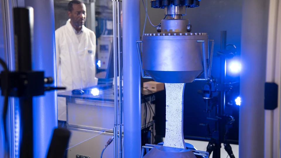
For 3D DIC, the same surface area must remain visible to both cameras throughout the test. If either camera cannot view it, the system cannot calculate results for that region at that point in time.
This is why it is essential to plan optical access for the full test sequence, rather than optimizing it for a single still image. The question is not simply, “Can we see it now?” It is, “Can we see it everywhere it may go?”
Sometimes the Answer Is a Mirror
For mirror-assisted DIC, use an optical-quality first-surface mirror to redirect the cameras’ view around an obstruction or toward a surface that faces away from them. The reflective coating sits on the front surface, avoiding the ghost reflections that conventional mirrors can introduce.
|
Depending on the setup, mirrors can help reveal:
|
 |
In other words, the mirror creates an additional camera view where placing a physical camera may be difficult, unsafe, or impossible.
Mirror-assisted DIC is more than a thought experiment. Researchers have demonstrated mirror-assisted multi-view DIC for dual-surface and panoramic shape, motion, and deformation measurements. Some configurations use a standard stereo camera pair with two plane mirrors; others use several mirrors to form multiple virtual views.
There is an important catch: a mirror is part of the measurement system, not a casual viewing aid. Its angle and position determine the virtual view, so you must characterize the reflected geometry and incorporate it into the measurement. It must provide a clear, stable reflection throughout the test without introducing unacceptable glare, loss of contrast, or image distortion.
A mirror does not let a camera see through an opaque object. A clear path must still exist from the surface to the mirror and another from the mirror to the camera. For stereo DIC, both required views must capture the reflected region with enough overlap to calculate the result.
When those conditions can be met, a properly engineered mirror arrangement can be an elegant solution, especially when the alternative is adding several cameras or rebuilding a fixture.
Other Ways to Work Around an Obstruction
Mirrors are useful, but they are not always the right answer. The measurement goal and the way the object moves should determine the approach.
Move the view. Reorienting the cameras, specimen, fixture, or lights is usually the simplest option. Do this before calibration, and make sure the new view still has enough room for the full motion.
Add another view. Synchronized DIC systems can cover different sides of a component at the same time. This is often the better choice for fast or nonrepeatable events, although it adds calibration and data-alignment work during post-processing.
Walk around a stationary structure. Photogrammetry, such as TRITOP, measures the 3D coordinates of target markers using images captured with a handheld camera. This makes it valuable for large structures requiring measurements from multiple camera positions. It works when the object remains static or can be held in repeatable states while the images are captured. It is not a substitute for simultaneous views during a fast-changing event. This is a useful option when coordinates and displacements are the quantities of interest; it does not provide the full-field strain measurements available with DIC.
Reach the feature instead of viewing it directly. For discrete coordinate measurements, an optically tracked touch probe can collect points in deep pockets, bores, or other features outside the cameras’ direct line of sight, as long as the tracking system can still see the probe’s reference markers.
Use a different technology. If the required feature is completely internal, no arrangement of cameras or mirrors will expose it. Computed tomography or another internal inspection method may be the better fit.
One practical rule helps narrow the choice: if every region must be measured during the same dynamic event, all necessary views must exist at the same time. If the part is stationary, the camera or sensor can often move between views.
Five Checks Before the Test Begins
Line-of-sight problems are much easier to fix while the setup is still flexible. Before the final test:
- Mark the critical regions. Decide what must be measured and whether you need full-field strain, 3D motion, or a few discrete points.
- Map the complete motion. Include expected deformation, rigid-body movement, possible failure behavior, and anything else that may enter the view.
- Install the real hardware. Check sightlines with grips, lights, cables, shields, chamber doors, and mirrors in their final positions.
- Run through the extremes. Use a dry run, CAD model, simulation, or mock-up to inspect every required camera view at the most demanding positions.
- Lock and verify the setup. After calibration, keep cameras, lenses, and any mirrors rigid. Confirm focus, lighting, contrast, and calibration quality before collecting critical data.
Post-processing can improve valid images. It cannot recover a surface the cameras never captured.
Make Optical Access Part of the Test Design
Line of sight is a real limitation, but usually manageable. Sometimes the solution is a better camera position. Sometimes it is a mirror, an additional camera, photogrammetry, or a different measurement method altogether.
The best option is much easier to identify before you lock in the fixture and test cell.
Planning a test with an obstructed view, large motion, or complex geometry? Talk with a Trilion engineer about the viewing strategy before you finalize the setup.